Inventor Sheet Metal Thickness Parameter

Autodesk Inventor Sheet Metal Flat Pattern Success Autodesk Inventor Sheet Metal Sheet Metal Fabrication

Solidworks Weldments Steel Storage Rack Steel Storage Rack Storage Rack Solidworks

Solved Sheet Metal Flat Pattern Width And Length Parametric Vba Autodesk Community Inventor
Setting Sheetmetal Thickness Autodesk Inventor Autocad Forums

Flat Pattern Length And Width In Parameters Iproperties Autodesk Community

From The Trenches With Autodesk Inventor Working With Unconstrained Imported Assembly Components Autodesk Inventor Inventor Autodesk

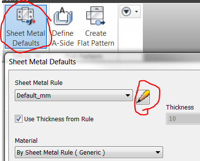
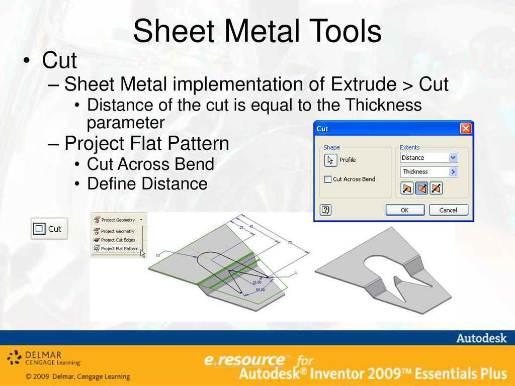
Named sheet metal rules combine sets of parameters and option selections which define how a particular sheet metal part is modeled in both the folded and flattened model state.
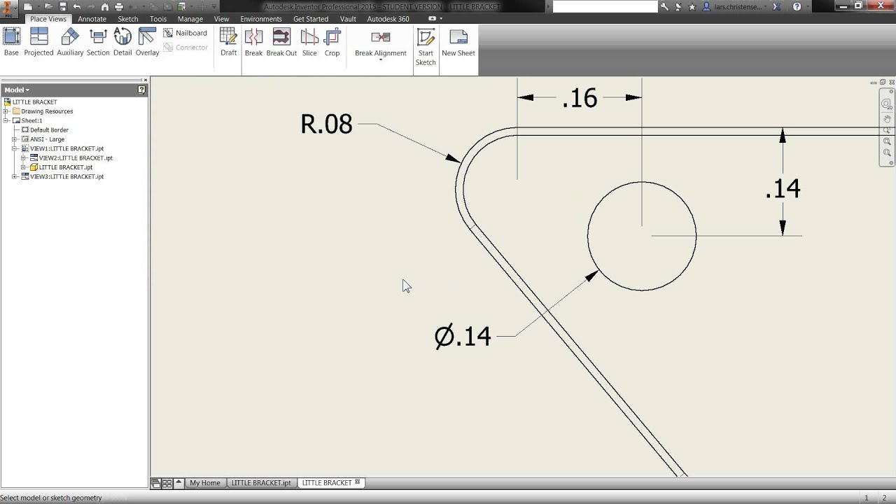
Inventor sheet metal thickness parameter.

Lost Link Variable On Sheet Metal Autodesk Community Inventor

Thickness Iproperty Used For Description Iproperty Of Part Autodesk Community Inventor

Autodesk Inventor 2013 Sheet Metal Parameters

Changing Sheetmetal Kfactor And Bendradius With Ilogic Autodesk Community Inventor

Solved Sheetmetal Autodesk Community Inventor

Inventor Sheet Metal Styles Youtube

Auto Detecting Sheet Metal Thickness New In Autodesk Inventor 2016 Youtube

Converting Models To Sheet Metal With Inventor Design Motion

Solidworks Cam Beta

Sheet Metal Parts Inventor Autodesk Knowledge Network

Pin On Metals

To Add Edit Or Sync A Sheet Metal Unfold Rule Inventor 2018 Autodesk Knowledge Network

Sheet Metal Annotations In Drawings Inventor 2018 Autodesk Knowledge Network

Solved Multi Body Solid W Multiple Sheet Metal Thicknesses Autodesk Community Inventor

Pin On Induction Pipe Bending Machine

Multi Cyclone Powder Coating Booth Fast Cleaning Automatic Powder Coating Booth Cyclone Recove Powder Coating Powder Coating Equipment Powder Coating System
Design And Production Of Plastic Shredder Youtube Shredder Machine Shredder Plastic Waste Management

Specifications Vicious Circle Cnc Homemade Cnc Diy Cnc Cnc

Yornew Personal Cnc Pcnc Small Cnc Machines Small Cnc Machine Diy Cnc Cnc Machine

To Create Holes Inventor 2019 Autodesk Knowledge Network

Creating A Custom Punch In Inventor Sheet Metal Synergis Engineering Design Solutions

People Are Part Of The Process For Machining Inconel Modern Machine Shop Machine Shop Metal Working Modern

Ilogic Rules External Vs Internal Autodesk Community Inventor

Change Your Sheet Metal Rule On The Fly Synergis

Solved How To Change Sheetmetal Thickness Autodesk Community Inventor
Chapter 10 Sheet Metal Design Ppt Download

Working With Inventor Sheet Metal Styles
Chapter 10 Sheet Metal Design After Completing This Chapter You Will Be Able To Perform The Following Start The Autodesk Inventor Sheet Metal Environment Ppt Download
Chapter 9 Sheet Metal Design Ppt Download

Embossing Text On A Part Youtube
Chapter 10 Sheet Metal Design Ppt Download

Exporting Thickness Parameter To Multiple Ipt Files Autodesk Community Inventor

To Work With Bend Features On Sheet Metal Inventor 2020 Autodesk Knowledge Network

Submarino Aguila Via Unblogged Ideias
Quick Inventor Tip Get Your Drawing Dimensions Automatically Youtube

Solved Change Sheet Metal Rule On A Solid Body With Ilogic Autodesk Community Inventor

Solved Ilogic Rule To Insert Sheet Metal Thickness Autodesk Community Inventor

Ilogic Rule For Material Thickness And Finish Autodesk Community Inventor

Extracting Inventor Sheet Metal Extents Via Ilogic Cadline Community

Autodesk Inventor 2017 Ilogic Change Sheet Metal Rule For All Parts In Active Assembly Youtube
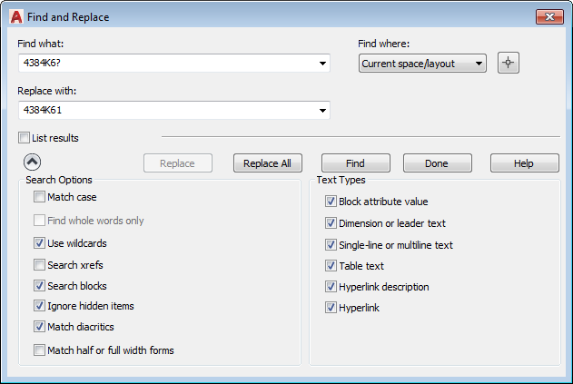
To Find And Replace Text Autocad 2019 Autodesk Knowledge Network

Solved Unable To Rip Sheet Metal Pipe Autodesk Community Inventor

The Difference Between K Factor Bend Allowance And Bend Deduction In Solidworks Youtube
Mod The Machine Iproperties
Source : pinterest.com
