Line Load Surcharge Retaining Wall Sheet
Surcharge Loads Types Spreadsheet

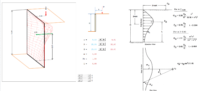
Line Load Surcharges Deepex
Surcharge Point Loads Spreadsheet
Http Files Engineering Com Download Aspx Folder 0d9bf08d 3a7d 4077 9f86 C26fc7d78d75 File Boussinesq Factor Of 2 Pdf

Combination Retaining Wall And Foundation Wall Structural Engineering General Discussion Eng Tips
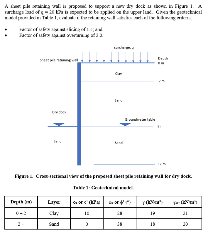
Solved A Sheet Pile Retaining Wall Is Proposed To Support Chegg Com

Surcharge location is 0 feet from shoring retaining wall height of retaining wall shoring is 10 feet traffic surcharge 𝑞 𝛾 𝑃 𝐻𝑒𝑞 30 pcf given in this example x 3 5 ft from table 1 105 psf.
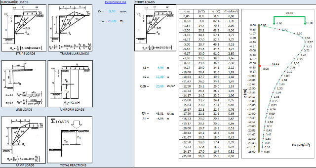
Line load surcharge retaining wall sheet.
Http Scholarsmine Mst Edu Cgi Viewcontent Cgi Article 3350 Context Icchge

There Are Numerous Kinds Of Loads And Forces That Acting On Retaining Wall They Are As F Construction Estimating Software Retaining Wall Retaining Wall Design

Surcharge Analysis Elastic Methods Strip Load
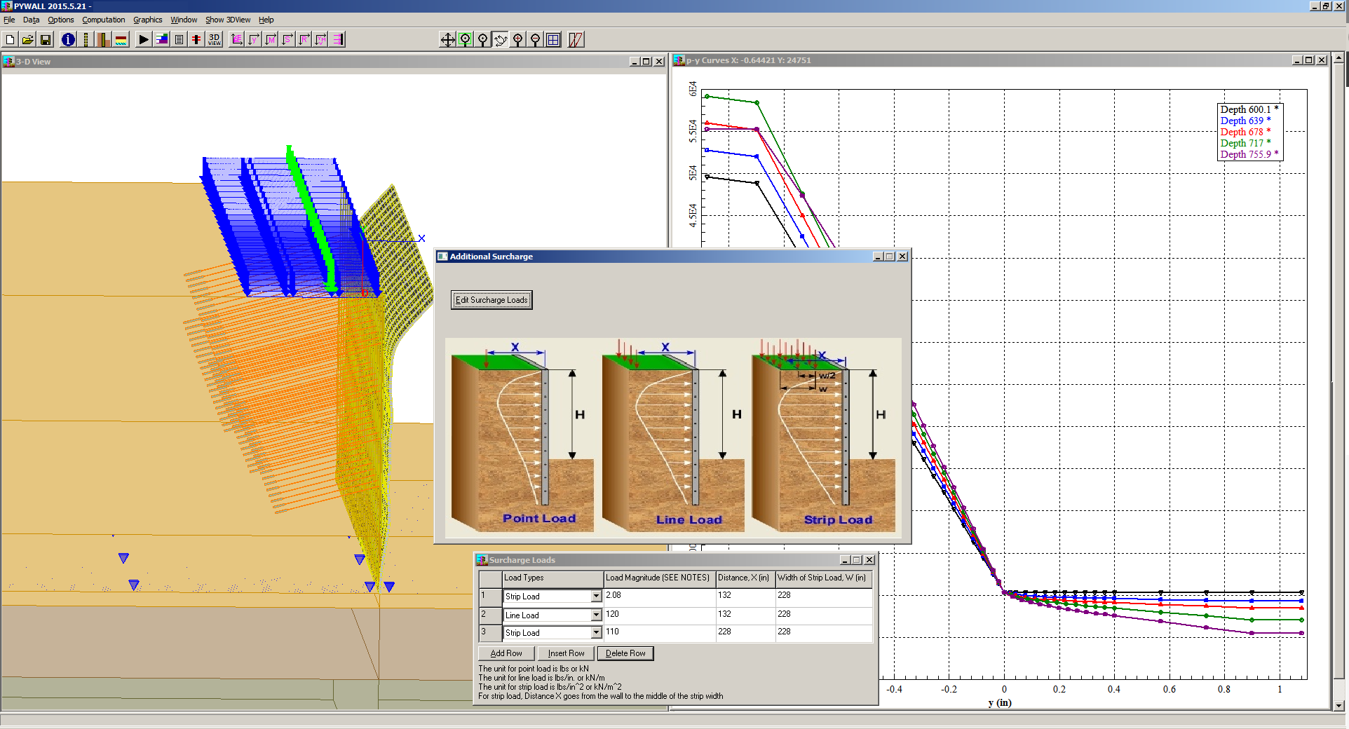
Pywall Ensoft Inc

Crane Load Surcharge On Retaining Wall Earth Retention Engineering Eng Tips
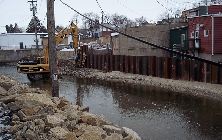
Can T Solve It Retaining Wall Next To Creek In Very Poor Soils Structural Engineering General Discussion Eng Tips

2 14 Point Line And Strip Surcharge Loads And Their Effects On Walls Linear Elasticity Stress Mechanics

Lateral Translation Of Retaining Wall Download Scientific Diagram

Lateral Earth Pressure From Surcharges And The 2x Factor Earth Retention Engineering Eng Tips
Effect Of Soil Wall Friction Angle On Behaviour Of Sheet Pile Wall Under Surcharge Loading Springerlink
Https Www Eiseverywhere Com File Uploads Bb5ea5ce29d0dcea6c48ae679641bd07 4 Kennyluudesignsoftheretainingwallstructures Pdf
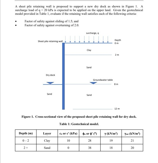
A Sheet Pile Retaining Wall Is Proposed To Support Chegg Com
Https Scholarsmine Mst Edu Cgi Viewcontent Cgi Article 2457 Context Icchge
Https Www Nh Gov Dot Org Projectdevelopment Bridgedesign Documents Completechapter4mar2016 Pdf

Retaining Wall Retaining Wall Civil Engineering Floor Plans

Loads And Forces Acting On Retaining Wall And Their Calculations Pdf
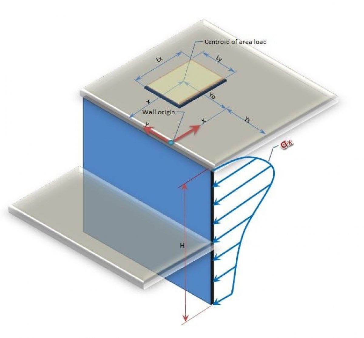
Surcharge Pressures Boussinesq Multiple Loads
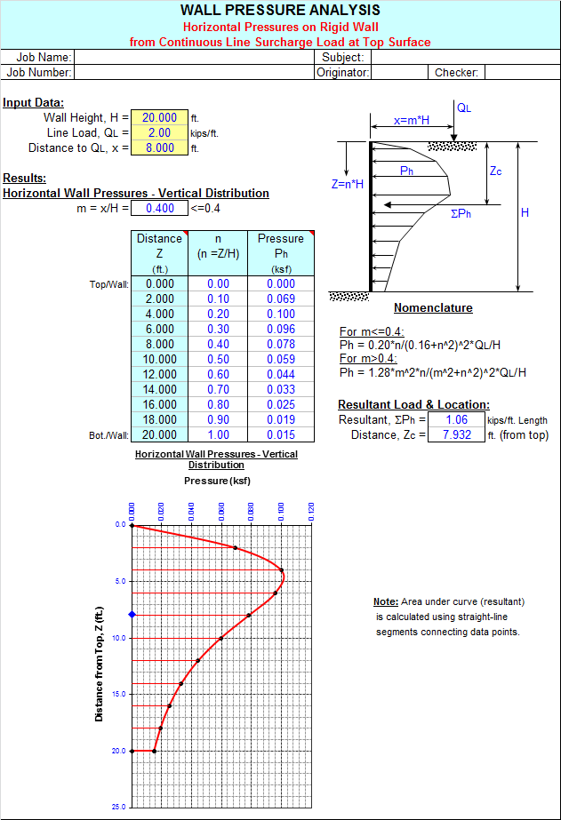
Wallpres Xls
Https Encrypted Tbn0 Gstatic Com Images Q Tbn 3aand9gcsakrlempqxja5hmyjgrxzkdni2ndmkntagcrd4cgne8erbxo0h Usqp Cau
Https Connect Ncdot Gov Resources Geological Geotech 20forms 2018 Retaining 20walls 20 E2 80 93 20soil 20nail 20wall 20with 20or 20without 20back 20slope 20 Typical 20and 20notes Pdf
Https Www Codot Gov Library Bridge Bridge Manuals Design Manual Bdm Section 11 2020 02 Pdf

Pdf Active Earth Thrust By Backfills Subject To A Line Surcharge

Lateral Earth Pressure Coefficients For Anchored Sheet Pile Walls International Journal Of Geomechanics Vol 12 No 5

Some Remarks On The Application Of The Cecp2 And Bs8002 Methods For The Analysis And Design Of Anchored Sheet Pile Walls Semantic Scholar

Concrete Retaining Wall Design Spreadsheet Retaining Wall Design Concrete Retaining Walls Retaining Wall Construction

Download Surcharge Earth Pressure 2012 Civil Engineering Software Spreadsheet Civil Engineering
Https Www Ensoftinc Com Products Pywall Doc Pywall Examples Manual Pdf
Performance Of A Two Tier Geosynthetic Reinforced Segmental Retaining Wall Under A Surcharge Load Full Scale Load Test And 3d Finite Element Analysis Semantic Scholar
Https Www Oasys Software Com Wp Content Uploads 2017 11 Greta19 2 Manual Pdf
Enercalc Version 5 8 Non Current Retired Version

When Should You Get Retaining Wall Permits And Engineering Plans

Effect Of Live Load Surcharge On Retaining Walls And Abutments
Analysis Of Non Yielding Basement Wall Adjacent To Strip Footing Semantic Scholar
Qualified Earth Retention Experts Terra Engineering Construction
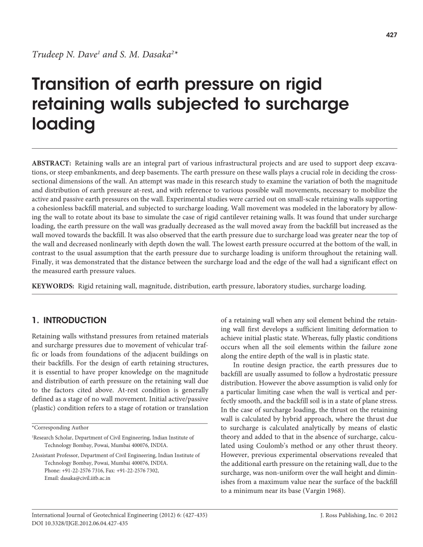
Pdf Transition Of Earth Pressure On Rigid Retaining Walls Subjected To Surcharge Loading

Retaining Wall Design Software Concrete Retaining Wall Design Retaining Wall Design Concrete Retaining Walls Retaining Wall
Https Www Ensoftinc Com Products Pywall Doc Pywall Description Sheet Pdf

Shoring Design Example Cantilever Sheet Pile Wall Si Units Deepex
Gale Academic Onefile Document Design Diagrams For The Analysis Of Active Pressure On Retaining Walls With The Effect Of Line Surcharge
Http Septa Org Business Bid 100k Detail 2018 1 17 00225 Apes Ad4 16sdc Pdf
Pdf Active Thrust On An Inclined Retaining Wall With Inclined Cohesionless Backfill Due To Surcharge Effect
Https Www Deepexcavation Com Uploads Documents Theory 20manual Eng 2011 Pdf
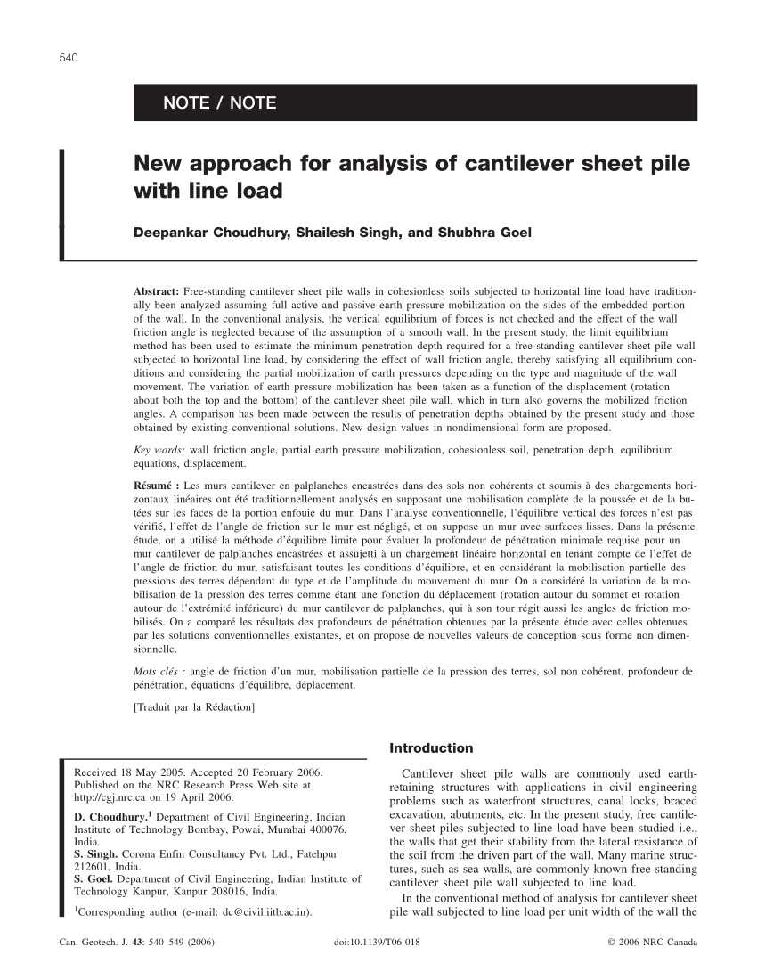
Pdf New Approach For Analysis Of Cantilever Sheet Pile With Line Load
Https Www Dot Ny Gov Divisions Engineering Technical Services Geotechnical Engineering Bureau Geotech Eng Repository Gdm Ch 17 Abuts Ret Walls Pdf
Source : pinterest.com
