Inventor Sheet Metal Flange Offset
Inventor Sheet Metal Flange Offset Autodesk Community

Solved Sheet Metal Flange Only On Partial Edge Autodesk Community Inventor

Inventor Sheet Metal Flange Bend Edit Offset Autodesk Community
How To Move An Inventor Sheet Metal Flange Along Edge Or Certain Length On Edge Inventor 2018 Autodesk Knowledge Network

Solved Sheet Metal With Partial Fold Autodesk Community Inventor

Solved Sheetmetal Flange Mitre Problem Autodesk Community Inventor
Create a contour flange.
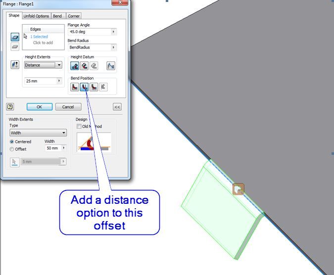
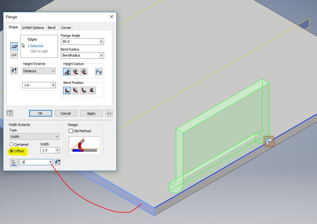
Inventor sheet metal flange offset.
Sheet Metal Angled Flange Problem Autodesk Inventor Autocad Forums

Solved Sheet Metal Flanges On Angles Autodesk Community Inventor

Overdue Improvements To Inventor Sheet Metal Autodesk Community

Solved The Extents Feature Is Grey Out In Contour Flange Of Sheet Metal Autodesk Community Inventor

Solved Sheet Metal Can T Flange Extruded Body Autodesk Community Inventor
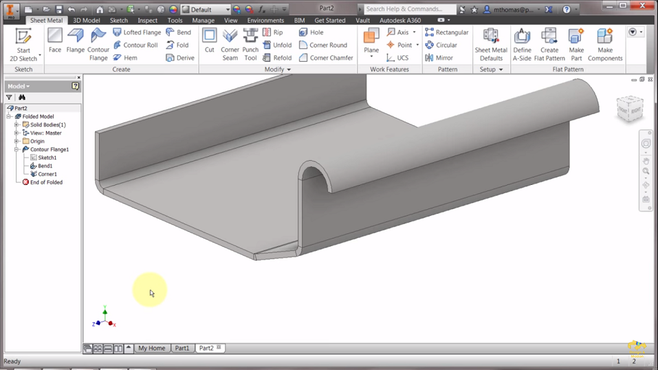
Sheet Metal Contour Flange Design Using Autodesk Inventor

Cannot Create Standard Sheetmetal Lap Joints Using Any Method Autodesk Community

Solved Inventor Sheet Metal Flange Creation Import Pro E Step File Has Bad Edges Autodesk Community Inventor
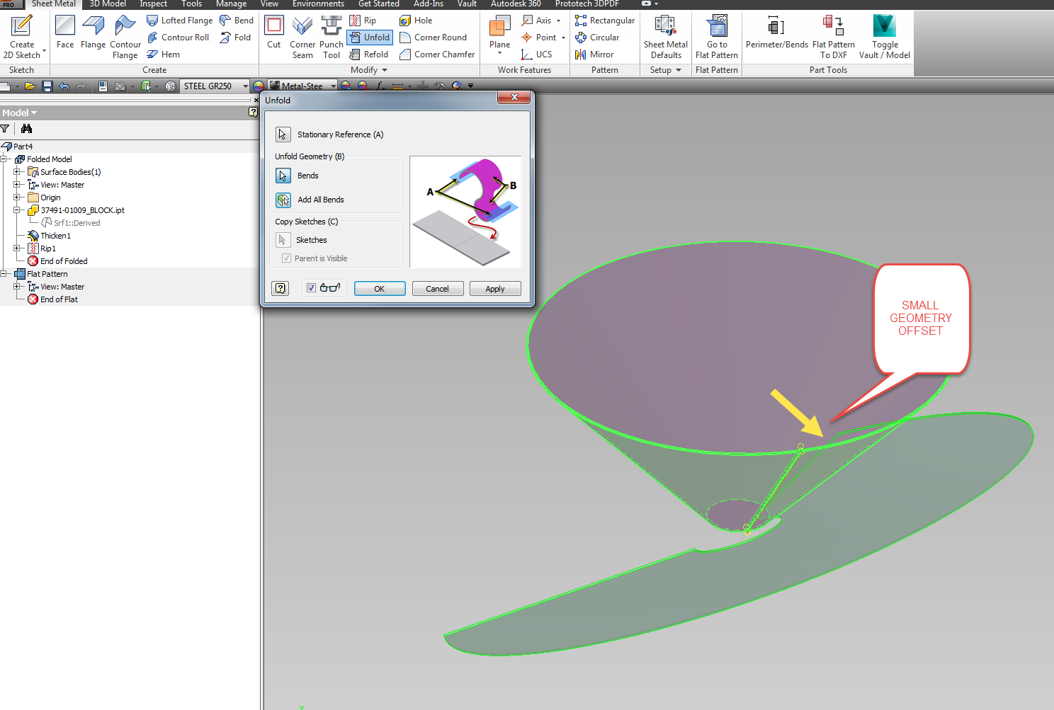
Unable To Unfold Refold A Lofted Flange Sheet Metal Part Inventor Autodesk Knowledge Network

To Work With Flanges In Sheet Metal Inventor 2021 Autodesk Knowledge Network

Solved Inventor 2019 Corner Seam Between Two Mulit Body Sheet Metal Solids Autodesk Community Inventor

Flange Feature In Inventor 2015 Youtube
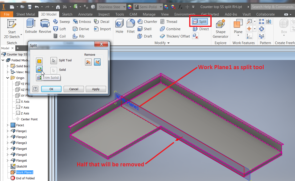
How To Split A Sheet Metal Part While Keeping The Ability To Create A Flat Part In Inventor Inventor 2018 Autodesk Knowledge Network
Solved Sheet Metal Flange Creating Non Symetric Flanges Autodesk Community Fusion 360

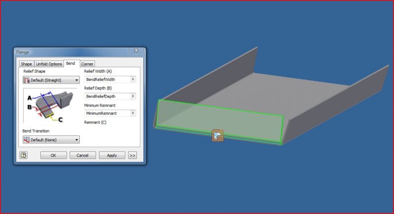
Solved Bend Position Control In Sheet Metal Autodesk Community Inventor

Solved Help With Corner Seam On A Compound Angle Autodesk Community Inventor

Extrude Sheet Metal Face In Both Directions Autodesk Community

Inventor Create Flat Pattern Youtube
Inventor Sheet Metal Alternative Applications Augi The World S Largest Cad Bim User Group

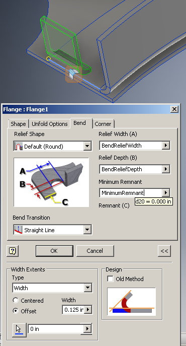
Autodesk Inventor 2013 Sheet Metal Flange Width Options

Solved Sheet Metal Flange Width Not Center Autodesk Community Inventor

Inventor Sheet Metal Contour Flange Tutorial Youtube

Solved Overlapping Flange For Seam Weld In Sheet Metal Autodesk Community Inventor

Solved Sheet Metal Corner Mitre Relief Shape Autodesk Community Inventor

Sheet Metal Self Intersecting Flanges Error Autodesk Inventor Autocad Forums

Bryan Cera Autodesk Inventor Sheet Metal Tabs And Fasteners

Inventor How To Use Lofted Flange Tutorial For Beginner Youtube

Solved Sheet Metal Offset Autodesk Community Inventor
Inventor Thicken Offset Command Tutorial Mechanicalengblog

Solved Nastran In Cad Midsurfaces How To Delete Autodesk Community Inventor Nastran

Solved Need Help Forming Sheet Metal Tabs Flanges Along Interior Internal Openings Autodesk Community Inventor

Using Offset In Inventor Youtube

Solidworks Sheet Metal Tutorial Panel Youtube Sheet Metal Sheet Metal Drawing Sheet Metal Work

Sheet Metal Flanges Fail To Miter Autodesk Community Inventor

Inventor Sheet Metal Folds Youtube

Solved Offset Flange Creates A Rip On Face If Bend Position Is From Adjacent Face Autodesk Community Inventor

About Corner Seams In Sheet Metal Parts Inventor 2018 Autodesk Knowledge Network

Solved Sheet Metal Relief Cut Autodesk Community Inventor

Add Flange To Sheet Metal Face Inventor Autodesk Knowledge Network

Autodesk Inventor Sheet Metal Ex1 Observation Vessel Trybotics

Cad Drawing With Inventor Autodesk Autocad Tutorial 4 Exercises Cad2601 Mechanical Engineering Youtube

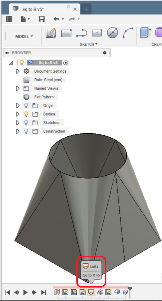
Solved Lofting Sheet Metal With 3d Sketch Autodesk Community Inventor

Inventor Sheet Metal Autodesk Inventor Autocad Forums

Solved How To Create Offset Flange In Sheet Metal Without Notch Autodesk Community Inventor
Source : pinterest.com
